Coolant Through Reamer: How Internal-Coolant Reaming Improves Hole Quality
News Details
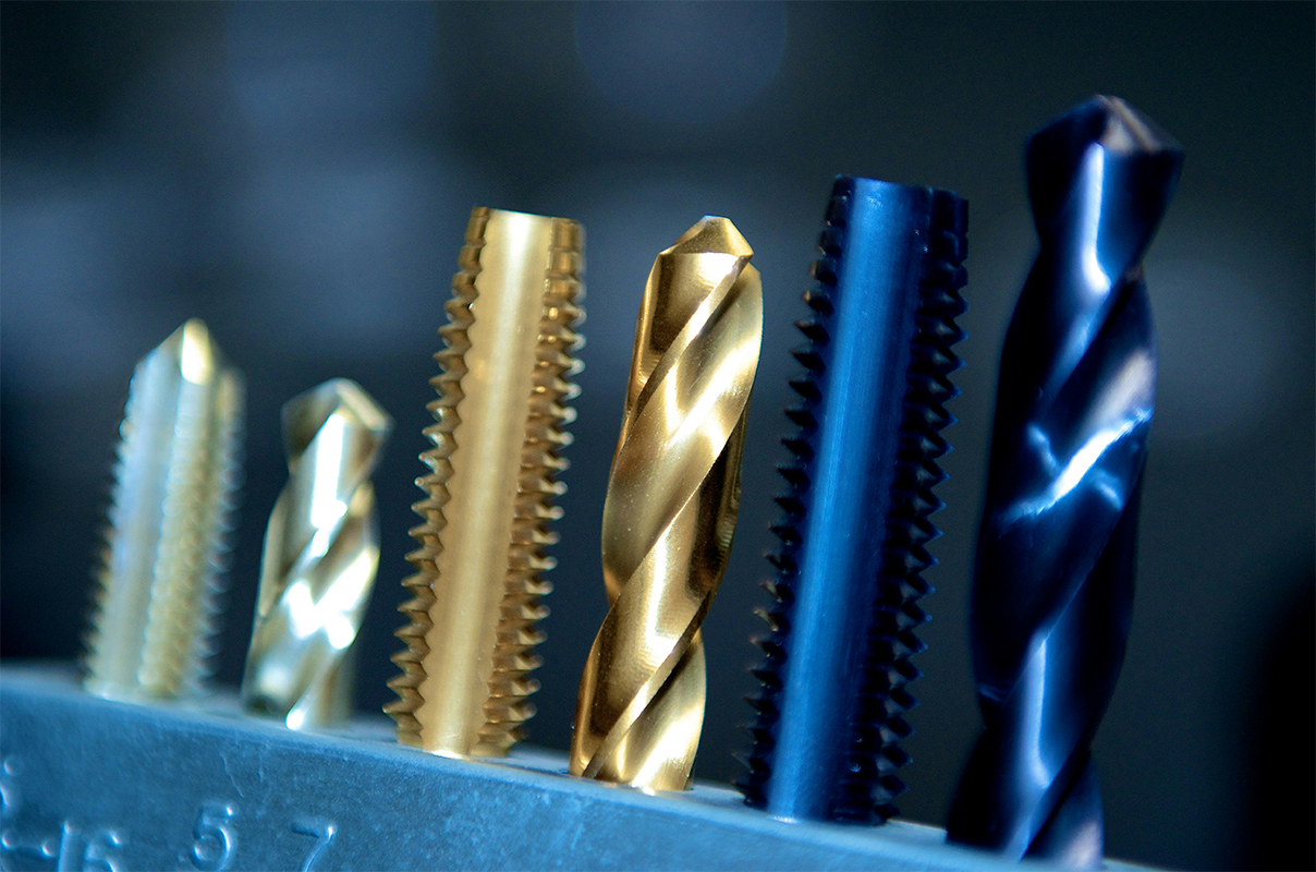
A coolant through reamer routes pressurized coolant through internal channels in the tool body and delivers it directly to the cutting edges. This guide explains how these tools work, the machine conditions they need, and how to evaluate tolerance, surface finish and tool-life claims before ordering.
What Is a Coolant Through Reamer?
A coolant through reamer is a precision reaming tool with internal coolant channels machined through the tool body. Pressurized coolant travels from the spindle through these channels and exits close to the cutting edges, either axially at the tool tip or radially through the flutes. Instead of relying on external flood nozzles to reach the cutting zone, the tool carries the coolant exactly where the cut happens.
This design matters most where external coolant struggles: deep holes, blind holes, and materials that produce stringy or adhesive chips. By flushing chips out of the hole and stabilizing the temperature at the cutting zone, a coolant through reamer helps hold diameter, protect the finished surface, and extend tool life in production reaming.
Why Carbide Coolant Through Reamers Dominate Precision Production
Most internal-coolant reamers sold for CNC production are made from solid carbide or carbide-tipped construction. Compared with high-speed steel (HSS), carbide offers much higher wear resistance, holds size longer during production runs, and supports higher cutting speeds. HSS remains a sensible choice for small batches and prototype work because it is tougher, less expensive, and easy to resharpen; for high-volume precision reaming, however, carbide is the usual substrate.
Vendors commonly specify ultra-fine or micro-grain carbide grades for these tools. Fine-grain carbide keeps a sharper cutting edge, which reduces cutting forces and helps both hole quality and edge toughness. For larger diameters, some manufacturers offer brazed-tip or steel-body designs with carbide tips, which deliver through-coolant performance at a lower cost than solid carbide bodies.
Machine Requirements for Through Spindle Coolant Reaming
A coolant through reamer only performs when coolant actually reaches the tool. The machine must have a through-spindle coolant (TSC) system, typically delivering 20–80 bar depending on the application. The toolholder must be sealed for internal coolant — coolant-sealed collet chucks or hydraulic chucks are common choices — because leakage at the shank-holder interface drops pressure before coolant reaches the cutting edges.
Coolant condition matters too. The internal channels in these tools are small, so the supply should be filtered, and water-soluble cutting fluid is usually maintained at around 5–8% concentration, free of particles that could block the passages. Shops without TSC spindles cannot run internal-coolant tools effectively; in that case, external flood coolant or MQL (minimum quantity lubrication) setups with compatible tooling are the realistic alternatives.
Deep Hole Reaming and Chip Evacuation
Chips are the main enemy in deep-hole reaming. As depth-to-diameter ratios grow past about 3:1, chips have no natural escape path; they pack into the flutes, get recut, scratch the bore, push the hole oversize, and can break the tool. Internal coolant solves this by forcing chips out of the hole continuously, before they can pack or be recut.
With adequate through-spindle coolant, buyers can expect stable results at depth ratios that conventional reaming cannot reach. Toolmakers commonly rate internal-coolant drilling to about 10×D and offer coolant-through reamers for hole depths up to roughly 8×D, with deeper applications moving to gun drilling or BTA processes. Two further benefits follow directly: stable cutting-zone temperature keeps the bore diameter consistent across a production batch, and lower variation in cutting force improves bore straightness in deep holes.
Coolant Pressure for Reaming
Pressure is the variable buyers most often underestimate. Reamer makers typically quote working pressures between about 300 and 1000 psi (20–70 bar) for through-coolant tools, and some specify 20–80 bar (300–1200 psi) depending on hole depth. A common guideline: around 20 bar is the minimum for effective chip flushing in holes up to 5×D, while holes in the 5–10×D range call for 40–80 bar. Below roughly 10 bar, chip evacuation becomes unreliable and tool life suffers.
| Hole depth | Typical pressure guideline |
|---|---|
| Up to 5×D | About 20 bar (≈300 psi) minimum for reliable chip flushing |
| 5–10×D | 40–80 bar (≈600–1200 psi) recommended |
More pressure is not automatically better. Excessive pressure can hydraulically expand the hole or damage delicate workpiece features, so follow the toolmaker's pressure recommendation for the specific diameter and depth, and make sure the pump delivers consistent volume, not just peak pressure.
Blind Holes vs Through Holes: Choosing the Right Coolant Delivery
Coolant-through reamers come in two delivery styles, and matching them to the hole type matters. Center-fed tools send coolant out of the front of the tool. On a blind hole, the coolant hits the bottom of the hole, floods back over the cutting edges and pushes chips up and out — which is exactly what a blind-hole operation needs. On a through hole, that front jet simply exits the far side without wetting the cutting edges, wasting the coolant. Flute-fed tools, where coolant exits radially through the flutes, are the right choice for through holes because they flood the cutting edges as the coolant exits sideways.
Spiral direction interacts with coolant delivery. A left-hand spiral pushes chips ahead of the tool, which suits flute-fed reamers in through holes; a right-hand spiral pulls chips back toward the shank, which complements center-fed reamers in blind holes. For environmentally focused production, MQL reaming with compatible tools is also an option, but chip evacuation must be watched closely because MQL supplies far less fluid volume than high-pressure coolant.
Coolant Through Reamer vs Standard Reamer
A standard reamer relies on external coolant and open flutes. For shallow through holes in easy materials it remains a sensible, lower-cost option. The table below summarizes the differences that matter in production:
| Feature | Standard reamer (external coolant) | Coolant through reamer |
|---|---|---|
| Cooling at the cutting zone | Low to medium | High |
| Deep-hole capability | Limited (≈3×D) | Up to ≈8–10×D |
| Chip evacuation | Poor in deep holes | Forced out with coolant |
| Tool life | Baseline | Roughly 2–4× longer |
| Upfront cost | Lower | Higher |
The practical rule: if holes are deeper than about 3×D, blind, or machined in sticky materials such as stainless steel or titanium alloys, the internal-coolant design usually pays for itself through fewer scrapped parts and fewer tool changes.
H7 Reamer Tolerance and Surface Finish
Bore quality is where internal coolant shows in the measured result. Manufacturers of carbide internal-coolant reamers commonly target H7 hole tolerance (IT7 class) in standard production, with H6 offered by some makers for more rigid setups. Reported surface finish values range from Ra 1.6 µm down to Ra 0.4 µm depending on material, feed and tool geometry. Low runout — often specified at 3 µm or less at the cutting diameter — is a key contributor, because runout makes the reamer cut unevenly and enlarges the hole.
These figures are supplier-reported capabilities, not guarantees for every setup. Achieving them consistently requires a rigid machine and workholding, correct reaming stock left by the pilot hole, stable coolant pressure, and feeds matched to the material. Ask suppliers for inspection reports and application data for your hole diameter and material before committing to a tolerance class.
Key Takeaways for Buyers
- Match the tool to the hole: center-fed for blind holes, flute-fed for through holes, and confirm spiral direction supports chip evacuation.
- Check the machine first: TSC pump pressure, sealed toolholders, filtration and coolant concentration are prerequisites, not upgrades.
- Size the pressure to the depth: about 20 bar for holes to 5×D and 40–80 bar for 5–10×D.
- Judge precision claims on evidence: ask for the tolerance class (typically H7), expected Ra range, runout specification and inspection reports.
- For deep, blind or sticky-material holes, compare total cost per hole — internal coolant usually wins on scrap, rework and tool changes.


