Carbide Cutting Tools Manufacturer: Grades, Manufacturing Process and Supplier Evaluation
News Details
What a Carbide Cutting Tools Manufacturer Actually Does
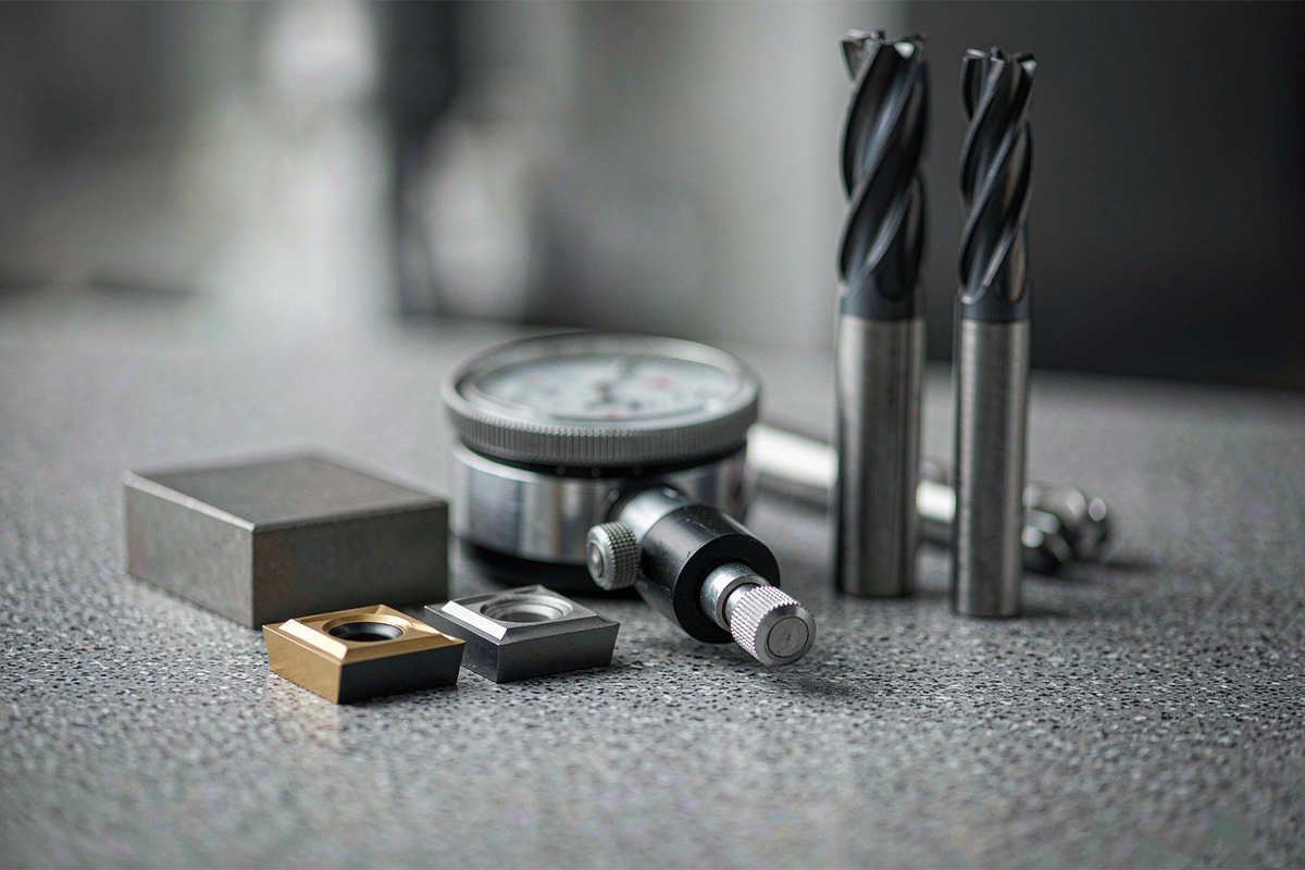
A carbide cutting tools manufacturer turns tungsten carbide powder into finished cutting tools: end mills, drills, reamers, inserts and special-form tools used across metalworking, mold making, automotive and aerospace machining. Behind that simple description sit two very different capabilities. The first is powder metallurgy — formulating, pressing and sintering the cemented carbide substrate. The second is precision toolmaking — grinding flutes and edges, applying coatings and verifying geometry at micron-level tolerances.
Understanding these capabilities matters to buyers because not every supplier performs every step in-house. Some manufacturers buy sintered rod blanks and focus on grinding and coating; others control the full route from powder to finished edge. Neither model is automatically better, but the division of responsibility determines who answers when a batch fails, and that is exactly what this article helps buyers evaluate.
How Carbide Cutting Tools Are Manufactured
The production route is a well-established powder metallurgy process with five stages.
- Powder preparation. Tungsten carbide (WC) powder is mixed with cobalt (Co) binder powder and, for some grades, small additions of other carbides. The mixture is wet-milled in ball mills for uniform dispersion, then spray-dried into free-flowing granules.
- Pressing. The granulated powder is pressed into shape by die pressing or isostatic pressing. At this stage the compact is fragile — often compared to chalk — and is called a green compact.
- Sintering. The compact is sintered in vacuum or hot-isostatic-pressing (HIP) furnaces, typically at around 1350–1500 °C. The cobalt melts and bonds the WC grains, and the part shrinks by roughly 18–20% in linear dimension, so shrink control is central to dimensional accuracy.
- Grinding. Sintered blanks, now nearly as hard as diamond, are ground on multi-axis CNC tool grinders with diamond wheels. Flute geometry, rake angle, relief angle and runout are established here; shank diameters are commonly ground to h5 or h6 tolerance.
- Coating and edge preparation. Thin PVD coatings, typically a few microns thick, are applied after edge honing or other edge preparation to raise hardness, heat resistance and anti-sticking performance.
Each stage adds value and each can introduce variation. Buyers evaluating a manufacturer therefore look not only at the final tool but at how each stage is controlled.
Tungsten Carbide Grades: Grain Size and Cobalt Content
The performance character of a carbide grade is set mainly by two variables: cobalt content and WC grain size. Cobalt provides toughness; WC provides hardness and wear resistance. Lower cobalt content and finer grains push hardness and wear resistance upward; higher cobalt content and coarser grains improve resistance to chipping and impact.
| Grade class | Typical WC grain size | Typical cobalt content | Typical application direction |
|---|---|---|---|
| Fine / submicron | 0.4–0.8 μm | 8–12% | General steels and cast iron; fine edges for finishing |
| Ultra-fine | 0.2–0.4 μm | 8–10% | Hardened steels, titanium, micro-diameter tools |
| Cobalt-rich toughened | 0.8–1.0 μm | 12–15% | Heavy interrupted cuts, roughing, unstable setups |
Hardness sampling on finished tools commonly falls in the HRA 88–93 range, and metallographic checks verify porosity and grain distribution. Buyers do not need to become metallurgists, but asking a supplier to state grain size, cobalt content and intended application for each grade is a reasonable and revealing request.
Carbide Tool Quality Inspection and Batch Traceability
Quality in carbide tooling is proven by measurement, not by appearance. A capable manufacturer's inspection system typically covers:
- Incoming and in-process controls — batch test reports for the carbide powder or rod stock, and process monitoring of pressing and sintering conditions.
- Geometric inspection — laser micrometers and automated optical inspection compare cutting diameter, rake angle, relief angle and helix angle against the approved specification; manual micrometers alone cannot verify a variable helix geometry.
- Runout control — total indicator runout affects how cutting load is shared between flutes; excessive runout concentrates load on one edge and shortens tool life sharply.
- Coating verification — coating thickness and adhesion checks, since coating parameters influence edge sharpness as well as wear life.
- Documentation — first-article inspection reports for new or custom tools, batch-level quality certificates for repeat production, and records that allow a batch to be traced back through production.
One caution on certificates: an ISO 9001 certificate confirms a structured quality management system. It does not by itself guarantee zero defects on a specific batch, which is why product-level inspection records matter as much as system-level certification.
Custom Carbide Tools for OEM Applications
Standard catalogs cannot cover every part feature. Deep cavities, stepped profiles, combined operations and non-standard radii often justify a custom or modified tool, and this is where a manufacturer's engineering capability shows.
A disciplined custom process runs in gates: drawing review, where material, geometry, datums, tolerances and critical inspection points are settled; sample approval, with measurement records and a representative machining trial; a pilot order, which checks repeatability across more than a single sample; and repeat supply, ordered against a frozen drawing revision with change notification agreed in advance. Buyers should also clarify who owns each design decision — the buyer may specify the finished part while the manufacturer proposes the cutting geometry, and both parties should approve the final tool drawing before production.
Carbide Cutting Tools Supplier Evaluation Criteria
Qualifying a supplier is easier when the evaluation is structured. The checkpoints below reflect common practice in sourcing reviews.
| Evaluation area | What to check | Why it matters |
|---|---|---|
| Process ownership | Which steps are in-house: grinding, coating, final inspection | Clarifies who is responsible when a batch fails |
| Material control | Grade specification and batch test reports for blanks | Inconsistent blanks produce unpredictable tool life |
| Grinding capability | CNC grinding equipment and wheel-wear compensation | Keeps geometry consistent across a production run |
| Metrology | Optical or laser inspection plus batch reporting | Turns quality claims into verifiable records |
| Supply reliability | Lead times, capacity headroom, reorder traceability | Protects production schedules at peak demand |
| Application support | Failure analysis and parameter recommendations | Resolves premature-wear problems instead of blaming the setup |
A controlled machining trial remains the strongest evidence. Fixed material, machine, holder and measurement rules, recorded across several tools and lots, reveal consistency in a way that a single perfect sample cannot.
Solid Carbide vs Indexable Carbide Inserts
Both formats use cemented carbide, but they suit different jobs. Indexable inserts are replaceable cutting tips clamped into holders; when an edge wears, the insert is rotated or replaced, which suits larger diameters, turning and high-volume facing where edge economy matters. Solid carbide tools are ground from a single blank; they offer higher rigidity, suit smaller diameters and complex geometries such as end mills and drills, and hold sharper, more precise edges for finishing.
The practical decision follows the operation: where edge replacement frequency and rigidity of the tool body dominate, indexable tooling often wins; where geometry precision, small diameters or sharp finished edges dominate, solid carbide is usually the better fit.
Carbide Tool Cost per Part
Unit price is a weak comparator for carbide tooling because tools with different lives produce different amounts of output. A simple break-even check helps: if Tool A produces a certain number of acceptable parts, Tool B must last longer in proportion to its price premium — its required life equals Tool A's life multiplied by the ratio of Tool B's price to Tool A's price. Below that break-even life, the cheaper tool wins on direct cost; above it, the premium tool does.
Direct tooling cost is still only part of the picture. Machine time per part, tool-change frequency, scrap risk and downtime caused by unpredictable failure all belong in the comparison. A slightly more expensive tool that runs predictably often lowers total cost per good part even when its purchase price is higher.
Key Takeaways for Buyers
A capable carbide cutting tools manufacturer is defined by controlled process stages, stated grade specifications, verifiable inspection records and disciplined handling of custom work. Buyers who ask which steps are performed in-house, request grade and batch documentation, and validate performance with controlled trials gather the evidence needed to compare suppliers on total cost per good part rather than unit price alone.


